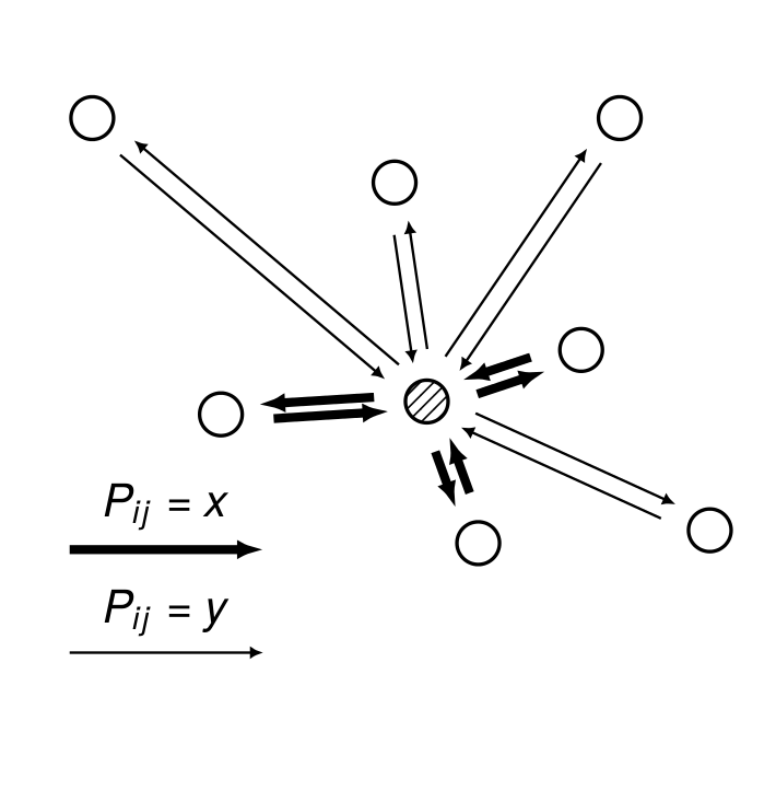
Fig 1A
The illustration

was created with TikZ using the following LaTeX code
\documentclass{standalone}

\usepackage{tikz}

\usetikzlibrary{arrows.meta,decorations.pathmorphing,
  backgrounds,positioning,fit,matrix, decorations, patterns}

\renewcommand{\familydefault}{\sfdefault}
\usepackage{tgheros}
\usepackage{sansmath}
\usepackage{siunitx}
\usepackage[english]{babel}
\usepackage[utf8]{inputenc}
\usepackage[T1]{fontenc}

\begin{document}


\begin{tikzpicture}[font=\sffamily\sansmath]

  \pgfmathsetmacro{\shift}{0.3ex}

  %%\node[circle,thick,draw=gray, dashed, minimum size=3.2cm] (src) at (0,0) {};

  \node[draw,circle, thick, pattern=north east lines] (src) at (0,0) {};

  %% \begin{scope}[every node/.style={circle,thick,draw, scale=1.}]
  %%   \node (src) at (0,0) {};
  %% \end{scope}

  \def\XR{2.6}
  \def\XL{3.2}
  \def\YU{3.}
  \def\YD{3.}
  \begin{scope}[every node/.style={}]
    \node (ur) at (\XR,\YU) {};
    \node (dr) at (\XR,-\YD) {};
    \node (dl) at (-\XL, -\YD) {};
    \node (ul) at (-\XL, \YU) {};
  \end{scope}

  \begin{scope}[every node/.style={circle,thick,draw, scale=1.}]
    \node (t1) at (1.2,.4) {};
    \node (t2) at (.4,-1.1) {};
    \node (t3) at (-1.6,-0.1) {};
  \end{scope}

  \begin{scope}[every node/.style={circle,thick,draw, scale=1.}]
    \node (d1) at (1.5,2.2) {};
    \node (d2) at (-2.6,2.2) {};
    \node (d3) at (2.2,-1.) {};
    \node (d4) at (-0.25,1.7) {};
  \end{scope}

  %% Legend
  \def\Llen{-1.75} % length of arrows
  \def\Lytop{-1.05} % y-dist from top
  \def\Lxright{-0.3} %x-dist from right
  \def\Lysep{-.8} %y-dist between two arrows
  \begin{scope}[every node/.style={}]
    \node (lul) at (-\XL-\Llen-\Lxright,-\YD-\Lytop) {};
    \node (lur) at (-\XL-\Lxright,-\YD-\Lytop) {};
    \node (ldl) at (-\XL-\Llen-\Lxright,-\YD-\Lytop-\Lysep) {};
    \node (ldr) at (-\XL-\Lxright,-\YD-\Lytop-\Lysep) {};
  \end{scope}


  \begin{scope}[every path/.style={-{Latex[length=2mm]},
                draw, solid, line width =0.7mm,
                shorten <= 5pt, shorten >=5pt}]

    \pgfmathsetmacro{\shift}{0.3ex}

    \path [transform canvas={xshift=\shift,yshift=-\shift}] (src) -- (t1);
    \path [transform canvas={xshift=-\shift,yshift=\shift}] (t1) -- (src);

    \path [transform canvas={xshift=-\shift,yshift=-\shift}] (src) -- (t2);
    \path [transform canvas={xshift=\shift,yshift= \shift}] (t2) -- (src);

    \path [transform canvas={xshift=-\shift,yshift= \shift}] (src) -- (t3);
    \path [transform canvas={xshift=\shift,yshift=-\shift}] (t3) -- (src);

    \path [shorten <= 0pt, shorten >= 0pt] (ldr) -- node[above]{$P_{ij}=x$} (ldl);


  \end{scope}

  \begin{scope}[every path/.style={-{Latex[length=1mm, width=1mm]},
                draw, solid, line width = 0.2mm,
                shorten <= 5pt, shorten >=5pt}]

      \path [transform canvas={xshift=-\shift,yshift= \shift}] (src) -- (d1);
      \path [transform canvas={xshift= \shift,yshift=-\shift}] (d1) -- (src);

      \path [transform canvas={xshift= \shift,yshift= \shift}] (src) -- (d2);
      \path [transform canvas={xshift=-\shift,yshift=-\shift}] (d2) -- (src);

      \path [transform canvas={xshift= \shift,yshift= \shift}] (src) -- (d3);
      \path [transform canvas={xshift=-\shift,yshift=-\shift}] (d3) -- (src);

      \path [transform canvas={xshift= \shift,yshift= \shift}] (src) -- (d4);
      \path [transform canvas={xshift=-\shift,yshift=-\shift}] (d4) -- (src);

      \path [shorten <= 0pt, shorten >= 0pt] (lur) --node[above]{$P_{ij} = y$} (lul);

  \end{scope}

\end{tikzpicture}

\end{document}